IDMR / Work / ADI Sintering Machine
Project · Industrial machinery · UBA-FADU

ADI Sintering Machine.

A desktop selective laser sintering (SLS) 3D printer, designed and built end-to-end as a team project at the Universidad de Buenos Aires, Facultad de Arquitectura, Diseño y Urbanismo. Sheet-metal chassis with a folded extruded-aluminium internal skeleton, a custom dosing-and-roller powder-handling mechanism, and a vertically-actuated build platform. From sketches and CAD through to a working physical prototype.

Sector
IndustrialSLS · Additive mfg.
Scope
TeamUBA-FADU · Cátedra Louzau
Outcome
PrototypeWorking physical build
Software
SolidWorksKeyShot · Adobe
About the project

A desktop SLS printer, built from scratch.

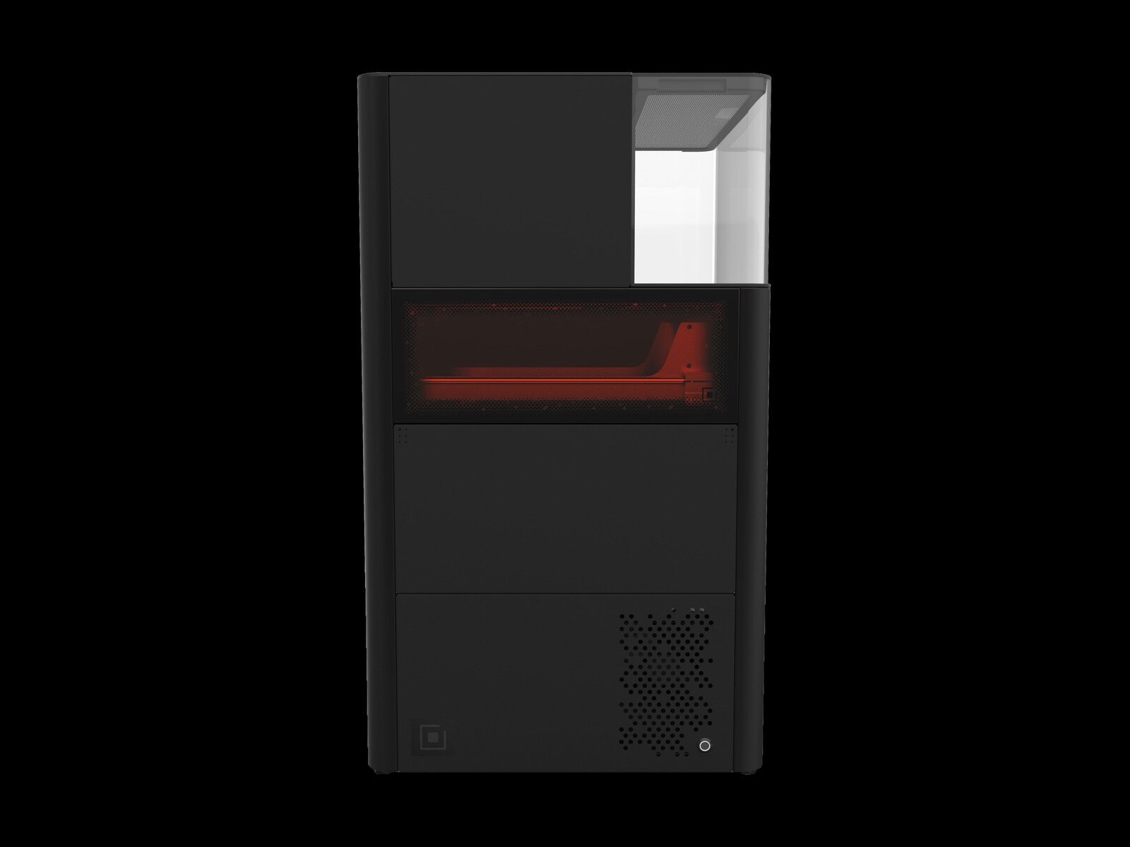
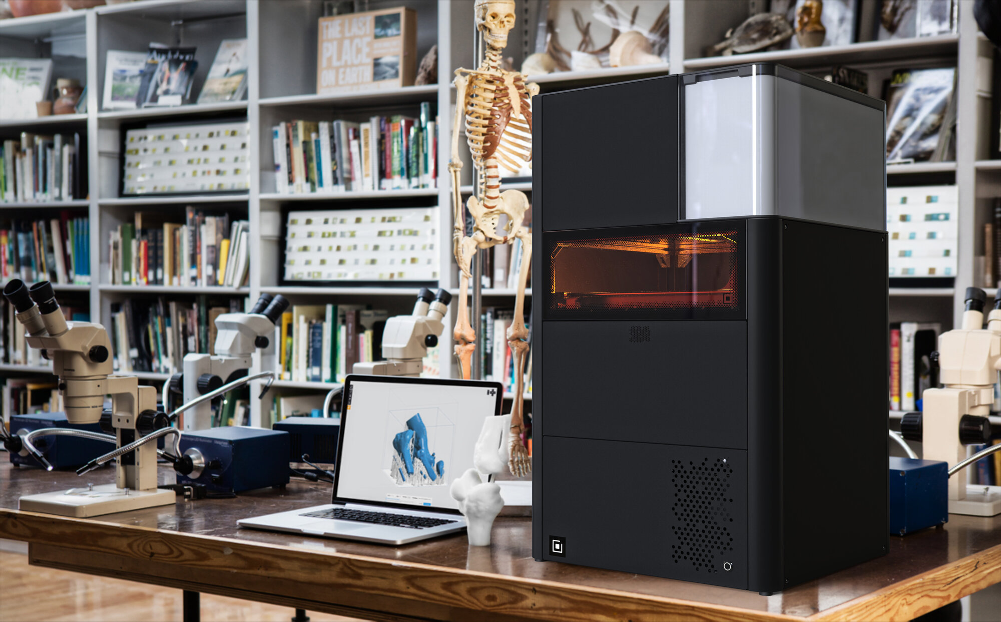
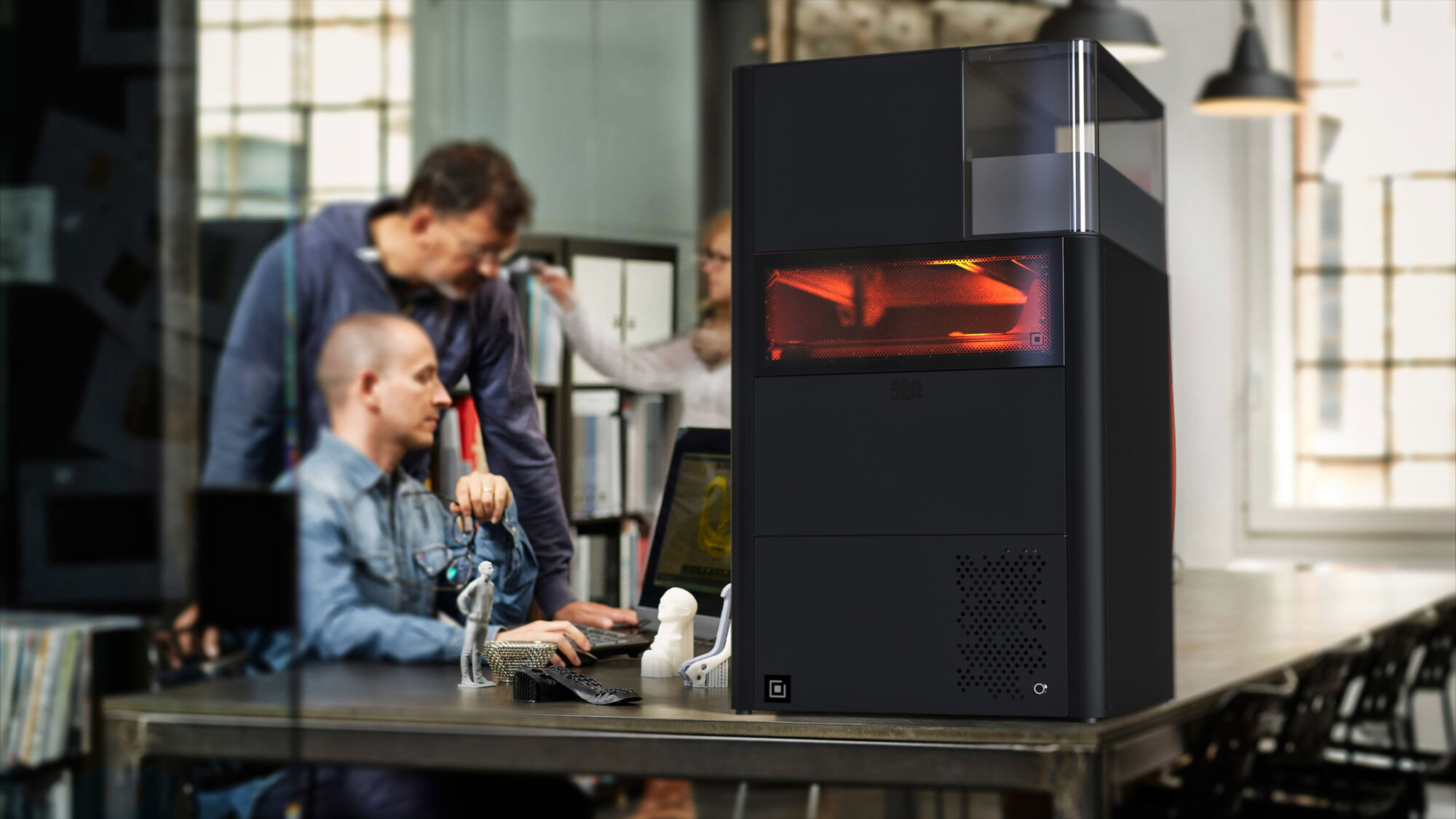
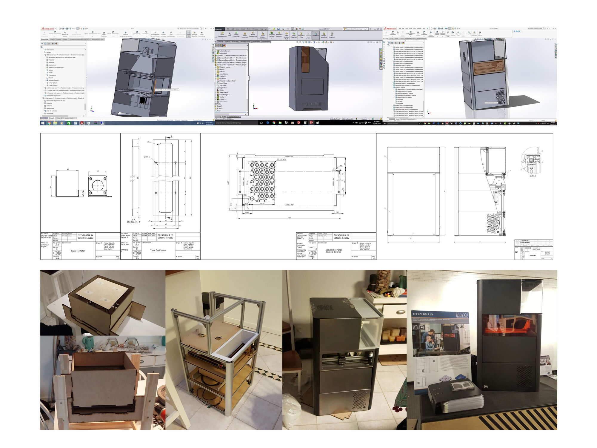
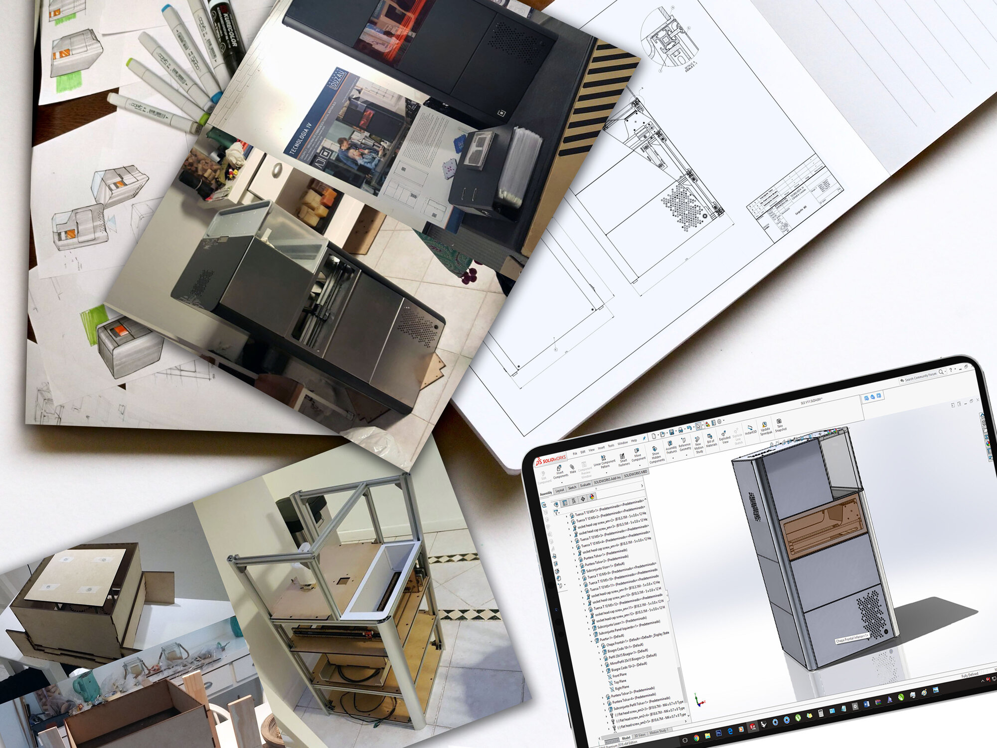
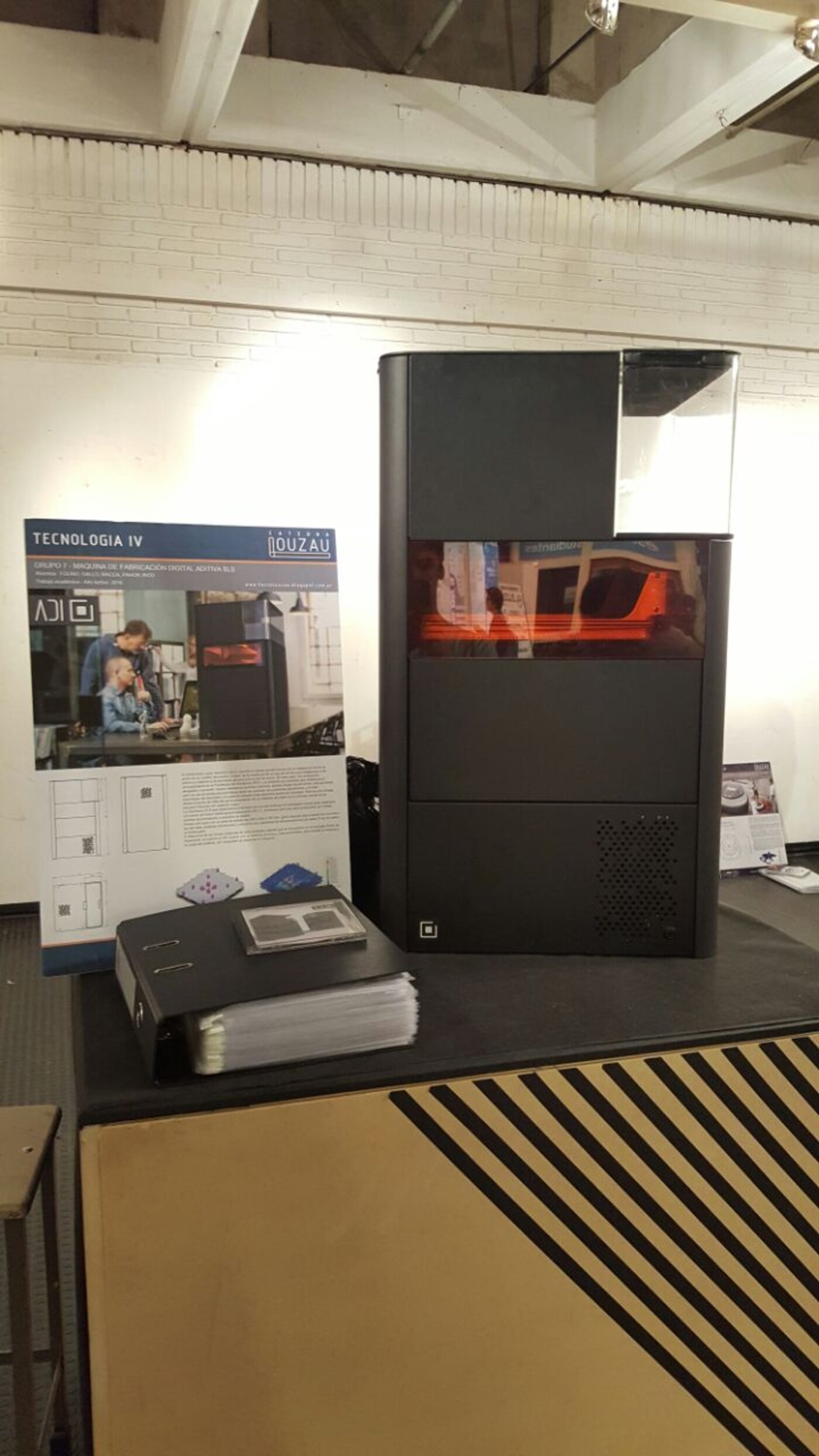
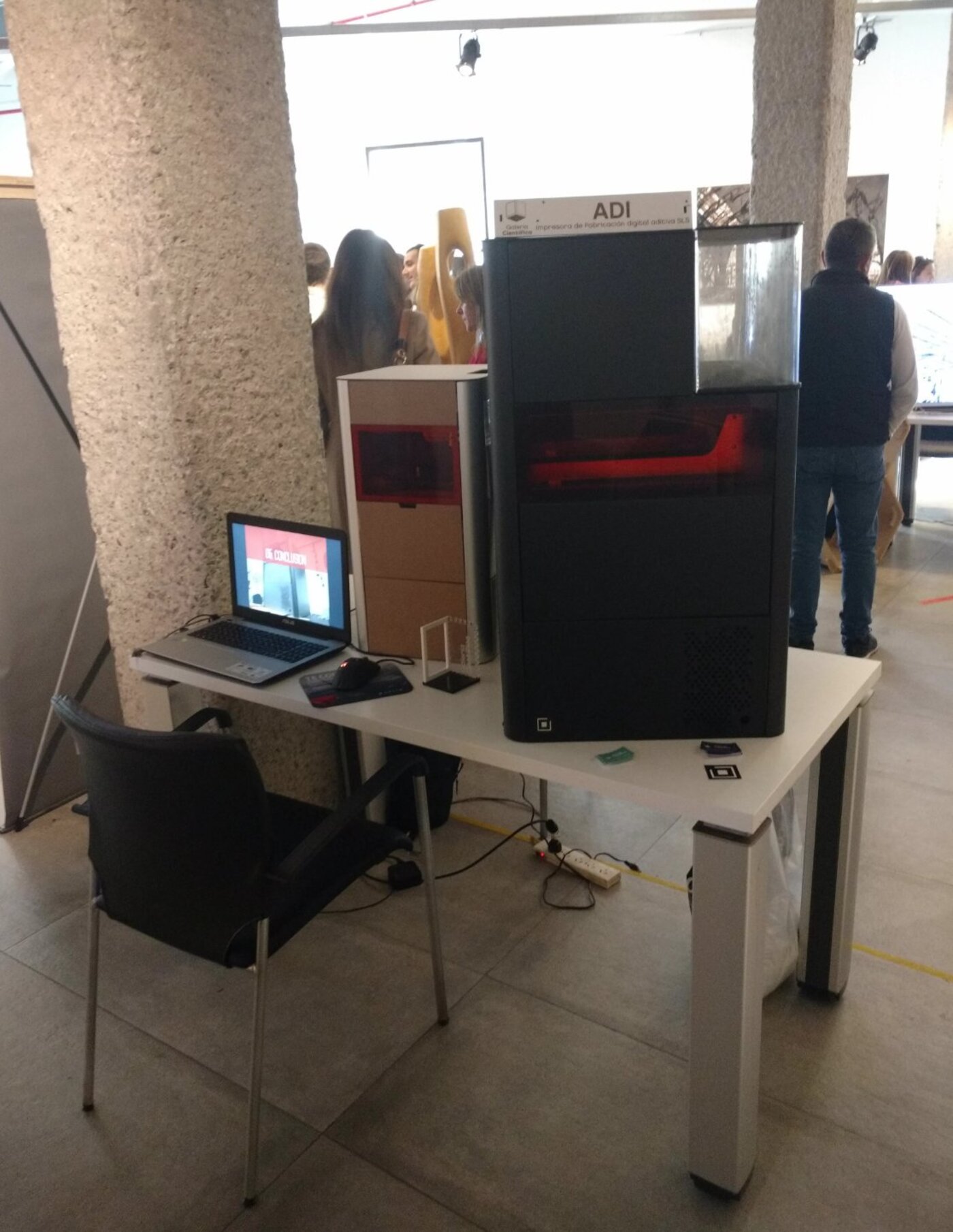
ADI is a selective-laser-sintering 3D printer designed to fit on a workbench. The brief — set by Cátedra Louzau within the Industrial Design programme at UBA-FADU — was to develop a piece of industrial machinery from first principles: identify the function, design the mechanism, draw every part, and build a working prototype out of real sheet metal and extruded profiles.

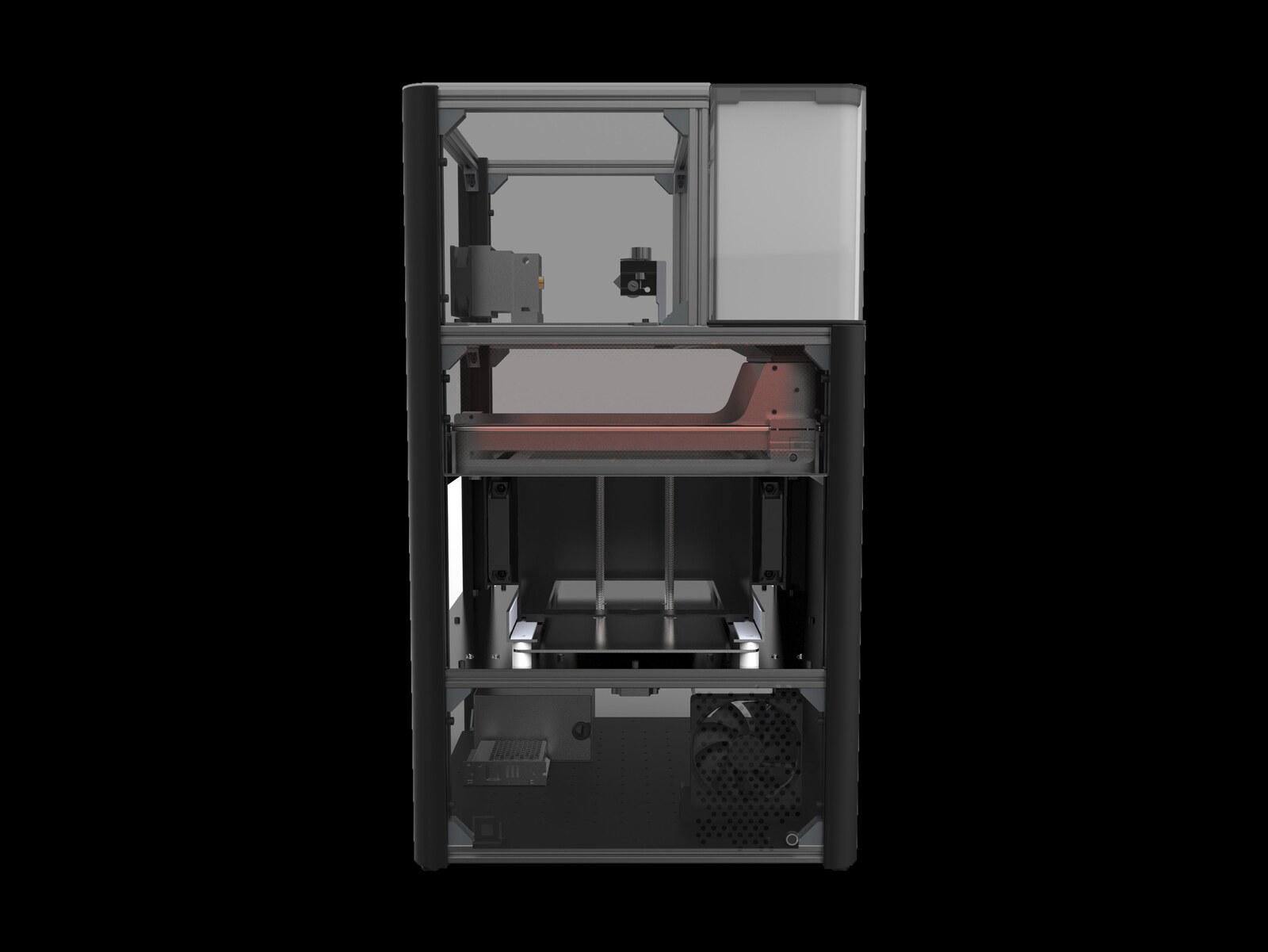
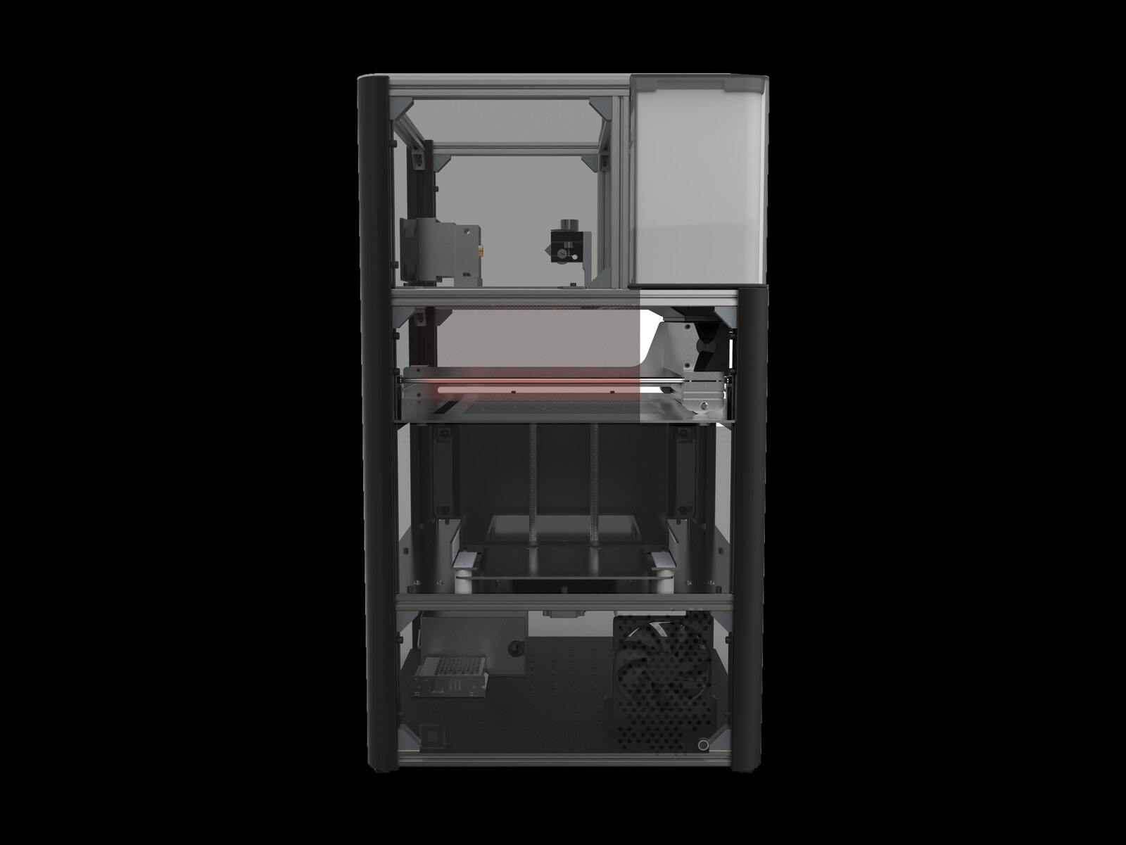
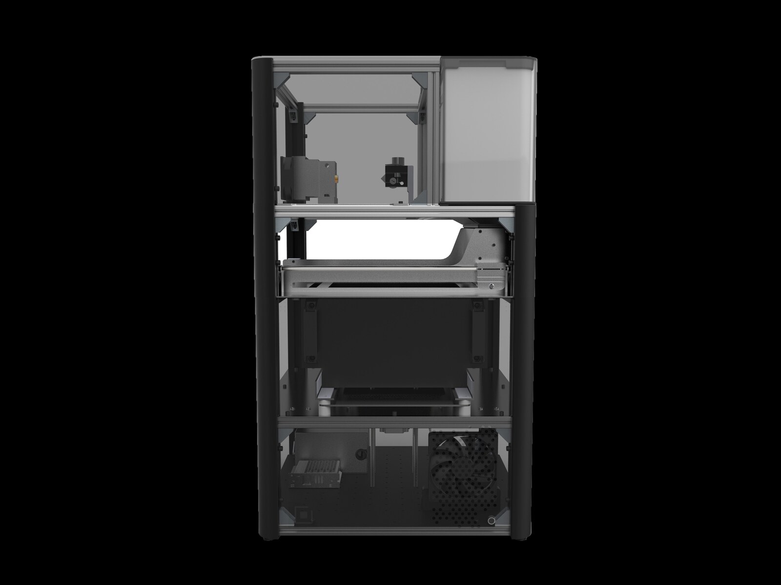
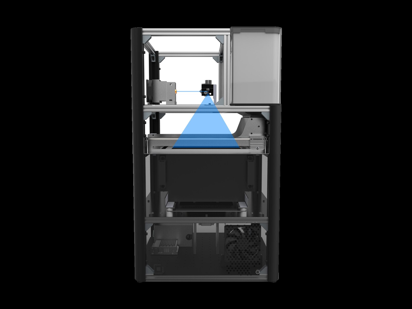
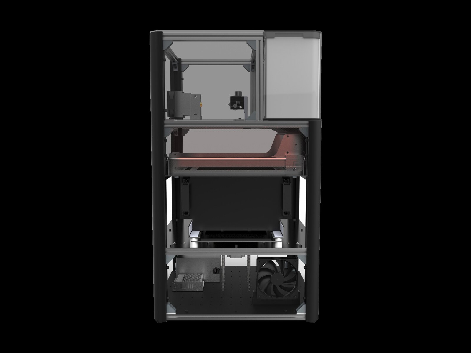
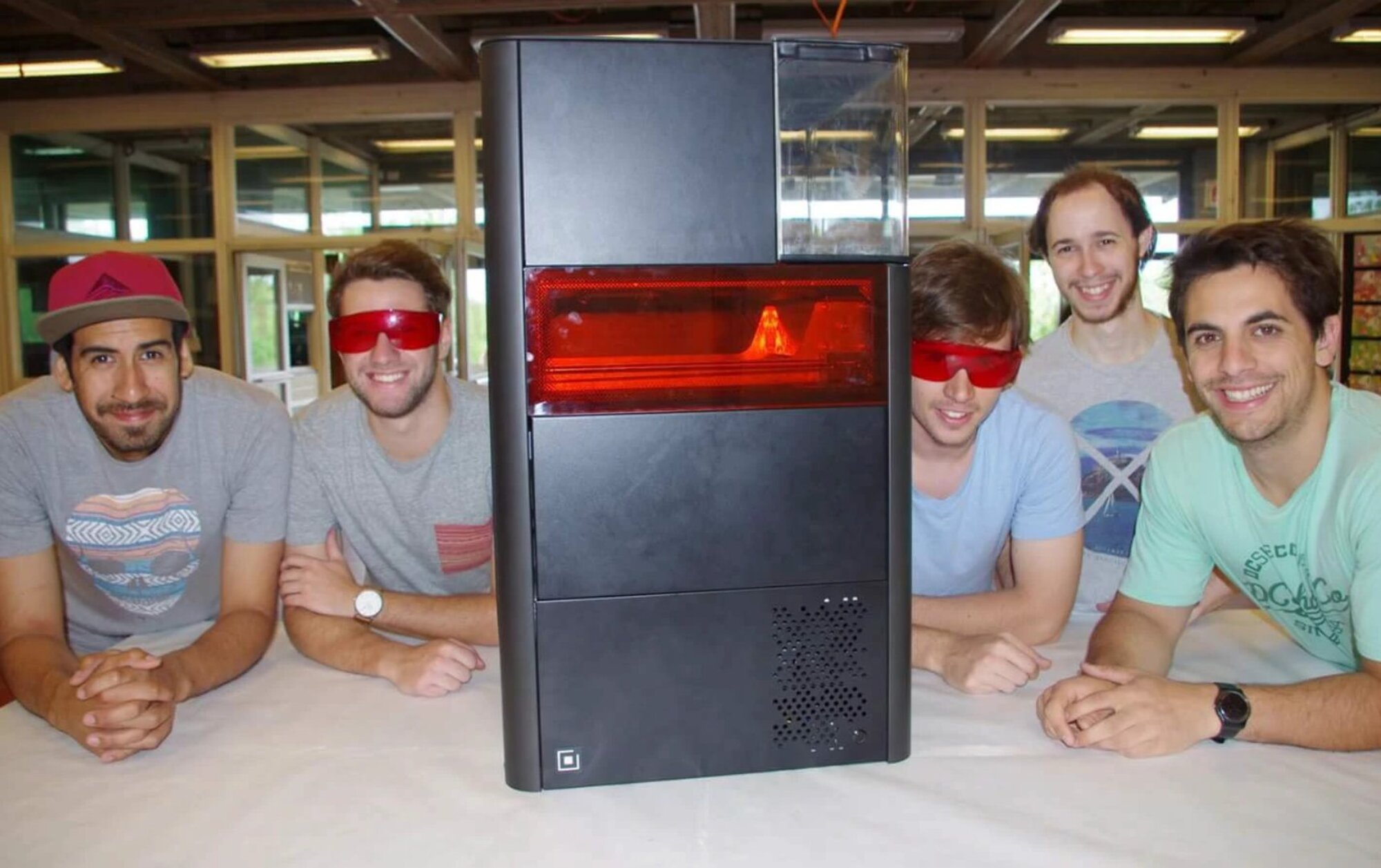
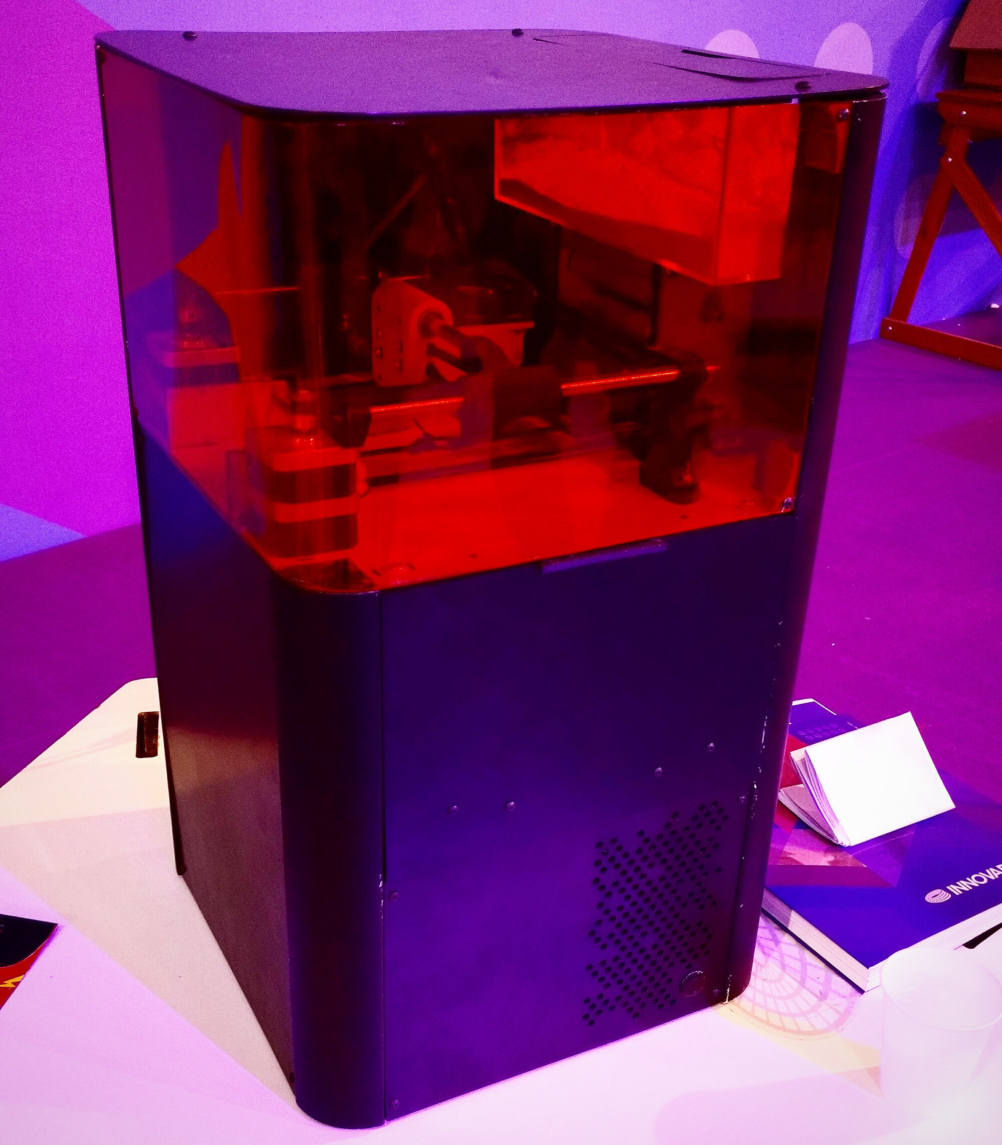
The architecture is straightforward by intent. A folded sheet-steel exterior wraps a 20-series aluminium-extrusion internal frame. The top houses a heated powder dispenser and a roller that sweeps a uniform layer of polymer powder across a heated build bed. A galvanometer-steered laser (in the visualisation shown as the blue cone) fuses the cross-section of the part. The build platform then drops one layer-thickness and the cycle repeats. Standard SLS; the design work was in compressing it into a desktop footprint that could plausibly sit next to a Formlabs or Sinterit on the same lab bench.

Team project — Universidad de Buenos Aires (FADU), Cátedra Louzau, Tecnología IV. Developed with Matías Macca, Agustín Folino, Leandro Gallo, and Nicolás Pahor. Sheet-metal engineering drawings, mechanism design, CAD assembly, prototype fabrication and final renders by the team. Exterior surface design and visualisation by Martín Rico.

Mechanism · The print cycle

Seven steps, one layer.

The internal mechanism follows a standard SLS cycle compressed into a desktop footprint. The animation below shows the seven discrete states — from sealed exterior idle, through bed-up, dispenser, roller, laser sintering, and bed-down — that the machine repeats once for every cross-section of the part being printed.

Designed so the user only ever interacts with the top loading bay and the front service door. Everything else stays sealed in operation — important both for thermal stability and to keep the very fine polymer powder contained.

ANIMATION · PRINT CYCLE
Print cycle · animated Empty → filled → bed up → dispenser → roller → sinter → bed down. Each state held for one second to keep the sequence readable; in operation, a real layer-pass is closer to half a second.
Cycle · Frame by frame

The same machine, opened up.

Each frame from the cycle animation, isolated. The first two states show the exterior with the skin closed; frames three through seven cut away the housing to expose the chassis and the moving mechanism — useful for explaining the print process without losing the product's actual form factor.

01 · IDLE
ADI sintering machine — exterior view, idle state with sintering window glow
Empty · idle The closed exterior. The red sintering window glows during operation; the powder hopper sits behind the lighter panel top-right.
02 · LOADED
ADI sintering machine — powder hopper filled, ready to print
Filled · ready Hopper loaded with polymer powder. The user fills it, closes the lid, and starts the print from the front controls — the rest is sealed for the duration.
03 · BED UP
ADI sintering machine cutaway — build platform raised to top position
Bed up · cutaway With the skin removed: build platform raised to the top of its travel. The leadscrews driving the bed are visible at the centre; the lower chamber houses the power supply and a single 120 mm cooling fan.
04 · DISPENSER
ADI sintering machine cutaway — powder dispenser releases material onto the platform
Dispenser · drop The dispenser releases a measured volume of powder onto the platform. Visible in the top compartment as the small motor-driven module on the left.
05 · ROLLER
ADI sintering machine cutaway — roller spreads powder across the build platform
Roller · spread The roller traverses the platform left to right, spreading the powder into a uniform layer. The roller assembly is the most mechanically demanding part of the design — flatness across the full bed width is non-negotiable.
06 · SINTER
ADI sintering machine cutaway — laser fires blue beam onto powder bed to fuse cross-section
Sinter · laser fires The galvanometer-steered laser (shown here as a blue cone) traces the cross-section of the current layer, fusing powder into solid polymer. The beam itself is invisible in operation — the cone is a diagrammatic representation.
07 · BED DOWN
ADI sintering machine cutaway — build platform drops one layer thickness ready for next cycle
Bed down · index Platform drops by one layer thickness — typically 100 to 200 microns for a desktop SLS. Cycle returns to step four and repeats until the part is fully built up.
Form · The exterior

Black box on a workbench.

The exterior was deliberately quiet. A piece of industrial machinery on a designer's or technician's desk has to disappear into the background — the work being made on it is the point, not the machine itself. So: matte black sheet-metal panels, a single visible structural radius on the right edge, a smoked-acrylic window over the active build area, and one square brand mark on the lower-left front face. Nothing else.

The two lifestyle renders below place the machine in the contexts it was designed for: a research lab and a design studio.

RENDER · CONTEXT
ADI sintering machine on a research lab bench with anatomy reference books and microscopes in the background
Lab · anatomy reference On a research-lab bench. The machine reads as one of many neutral instruments around it — the brief, deliberately.
RENDER · CONTEXT
ADI sintering machine on a design studio table with people working on 3D models in the background
Studio · design office On a design studio worktop. The active sintering window glow is the only thing that draws the eye in the room.
Process · From CAD to physical build

It actually got built.

The course requirement that made this project unusual: a working physical prototype, not just a render. The team produced full SolidWorks engineering drawings for every sheet-metal part, had them laser-cut and folded at a local shop, assembled the aluminium-extrusion internal frame, and arrived at a poster-and-machine final delivery photographed on the floor of the studio.

The board below shows the development arc — CAD assemblies, dimensioned engineering drawings, and the physical prototype at three stages of build, ending with the final delivery alongside the project poster.

DOCUMENTATION · DEVELOPMENT BOARD
Process board showing SolidWorks CAD screenshots, dimensioned sheet-metal engineering drawings, and photos of the ADI physical prototype at three build stages with final delivery poster
CAD → drawings → build Top row: SolidWorks assemblies through three iterations. Middle row: dimensioned sheet-metal drawings (motor bracket, dispenser cover, lower front panel, full assembly). Bottom row: physical prototype build, from MDF mock-up through to the final delivered machine alongside the project documentation poster.
DOCUMENTATION · MOODBOARD
Desk moodboard with marker sketches of the ADI machine, prototype photos, engineering drawing, and SolidWorks model on an iPad
Sketches · prototype · CAD Marker-and-paper concept sketches, prototype-stage photographs, a folded engineering drawing, and the final SolidWorks assembly on an iPad — all the working materials in one frame.
Walkthrough · Video

Watch the machine in motion.

A short walkthrough of the ADI prototype — the exterior, the operator interactions (top loading, front service door), and a quick pass through the print cycle as it runs.

VIDEO · YOUTUBE
Walkthrough · YouTube Recorded during the final delivery of the project — exterior tour, operator interaction, and a live print cycle.
Reality · The physical build

From render to the room.

The reason this project gets remembered: the renders are gorgeous, but the machine actually exists. The four photographs below show the prototype as delivered — alongside the team, at the project's final review, and later on display at an exhibition where it was selected to represent the cátedra.

Some of the proportions in the physical prototype shifted slightly from the final renders (the upper hopper section in particular reads taller in person), but every major design move — the sealed exterior, the lit sintering window, the square brand mark on the lower-left, the brushed-metal accent edge on the right — made it through to the built object.

PHOTO · THE TEAM
The ADI project team — five team members posing with the finished prototype machine on a table, two wearing red safety glasses for the active sintering window
The team · final delivery Matías Macca, Agustín Folino, Leandro Gallo, Nicolás Pahor, and Martín Rico — with the finished prototype. Red safety glasses for the active sintering window.
PHOTO · FINAL REVIEW
The ADI machine on a presentation table during final project review, next to a project poster bound documentation and product samples
Final review The machine on the presentation table next to the project poster and the bound documentation binder. The square brand mark on the front face is the only graphic on an otherwise neutral object.
PHOTO · EXHIBITION
ADI machine on display at an exhibition, on a table with a laptop showing the project presentation, with visitors in the background
Exhibition · Galería Científica Selected for an exhibition after the course concluded, displayed alongside a second project in the cátedra's group. Project headline reads "ADI — impresora de fabricación digital aditiva SLS".
PHOTO · DETAIL
Close-up of the ADI prototype with red-tinted acrylic window revealing the internal sintering mechanism — laser galvanometer module, roller assembly, and powder bed visible inside
Detail · through the window Closer view of the sintering window. The red-tinted acrylic is structural and functional — it shields the operator from the laser wavelength while letting you see the mechanism work. Visible inside: the galvanometer head, the roller carriage, and the powder bed below.
External · Full gallery

See the complete project.

The full ADI image set, including additional process photos, detail renders, and exploded views, lives on Behance.

VIEW ON BEHANCE ↗

Working on something similar?

Industrial machinery, lab equipment, or a desktop hardware product that has to be both engineered and beautiful — send a brief and we'll come back within two working days.

Request a quote